While waiting for my Octane2 to arrive, I started preparations and made myself a 13W3 to DSUB Adapter.
There are plenty of adapters on the market, but most of them are either:
- wrong way (to use 13W3 monitor with VGA Video card)
- SUN-specific (some of them work with older SGI machines, but due to wrong routing of a couple signals, those do not work with newer machines like Octane)
- There are (but difficult to find) SGI-specific adapters with only A1,A2,A3 signals routed.
So, what to do – there are usually few options:
- Buy SUN adapter, and modify it to work (this usually involves dissecting the molded plug and rerouting some cables inside).
- Buy a 13W3 -> BNC adapter, along with BNC -> VGA (that’s the best solution if you have monitor with BNC).
- Make your own :)
Being a DIY guy, I decided to sacrifice some cheap old VGA cable I found in the box, bought a couple of 13W3 plugs with mini-BNC’s and started soldering. I was actually surprised I could buy 13W3 plugs, sockets and those mini-BNC’s with no problem at all (I did have to ask the clerk for more because the boxes in the store were empty – they had a bunch in stock – if I recall, 100 JPY for each mini-BNC + 300 JPY for the plug).
The operation is fairly simple:
- Strip off the D-SUB cable on one end – if it’s molded be careful not to cut yourself – there will probably be metal shielding which really likes to cut your fingertips :P (which hurts A LOT).
- Find out which cables are for R,G,B and their shielding – even my cheap cable had them clearly separated each with it’s own shielding (if yours doesn’t – throw it away and buy another one – you won’t get good picture without each color properly shielded), Red had pink color, Blue was Blue, and Green was white – so finding out what is what wasn’t hard either.
- Put BNC protective caps first and strip off the shielding from each of those 3 cables. My cable had foil with outer plastic wrapping on each.
- Make sure you have the caps – otherwise you will end up desoldering and probably melting the cable.
- Do you really have the caps on ?
- Solder the signal cables into 13W3 mini-BNC’s, then wrap the shielding around nicely and solder into each BNC outer casing,
- You may need to file the shielding solder nice and round so that cap has snug fit – if you do it well, it will fit all the way with a little click at the end.
I didn’t buy the plastic enclosure yet, looking at dimensions of my plug, any DB25 sized should work.
My small advice – DO NOT insert mini-BNC’s into the plug (I was tempted and this made it a bit harder, also you can’t remove it once it’s in place), solder them while loose.
Use third hand – if you do put mini-BNC’s into the plug – they rotate which just makes it harder.
At every step, make sure you didn’t melt signal’s isolation and there is no short between any of the pins.
Once you’re done, verify the cable:
- A1 (RED) signal should lead to pin 1 (top left) on the DSUB.
- A1 (RED) shielding should lead to pin 6 (middle row left) on the DSUB.
- A2 (GREEN) signal should lead to pin 2 (top 2nd from the left) on the DSUB.
- A2 (GREEN) shielding should lead to pin 7 (middle row 2nd from the left) on the DSUB.
- A3 (BLUE) signal should lead to pin 3 (top 3rd from the left) on the DSUB.
- A3 (BLUE) shielding should lead to pin 8 (middle row 3rd from the left) on the DSUB.
That’s all – 3 shielded cables should to the trick.
In addition, I would also recommend soldering cable’s outer shielding into the metal casing of the plug. (If you don’t – it will probably work, but you will end up with some interference.)
If you fancy (or if you monitor doesn’t support Sync-On-Green), you may need to solder Sync signals into respective ports (I didn’t need to, and this has not been confirmed to work):
Pin 3 – C. Sync / Gnd goes to pin 10 on DSUB
Pin 4 – H. Sync goes to pin 13 on DSUB
Pin 5 – V. Sync goes to pin 14 on DSUB
Some pictures below:
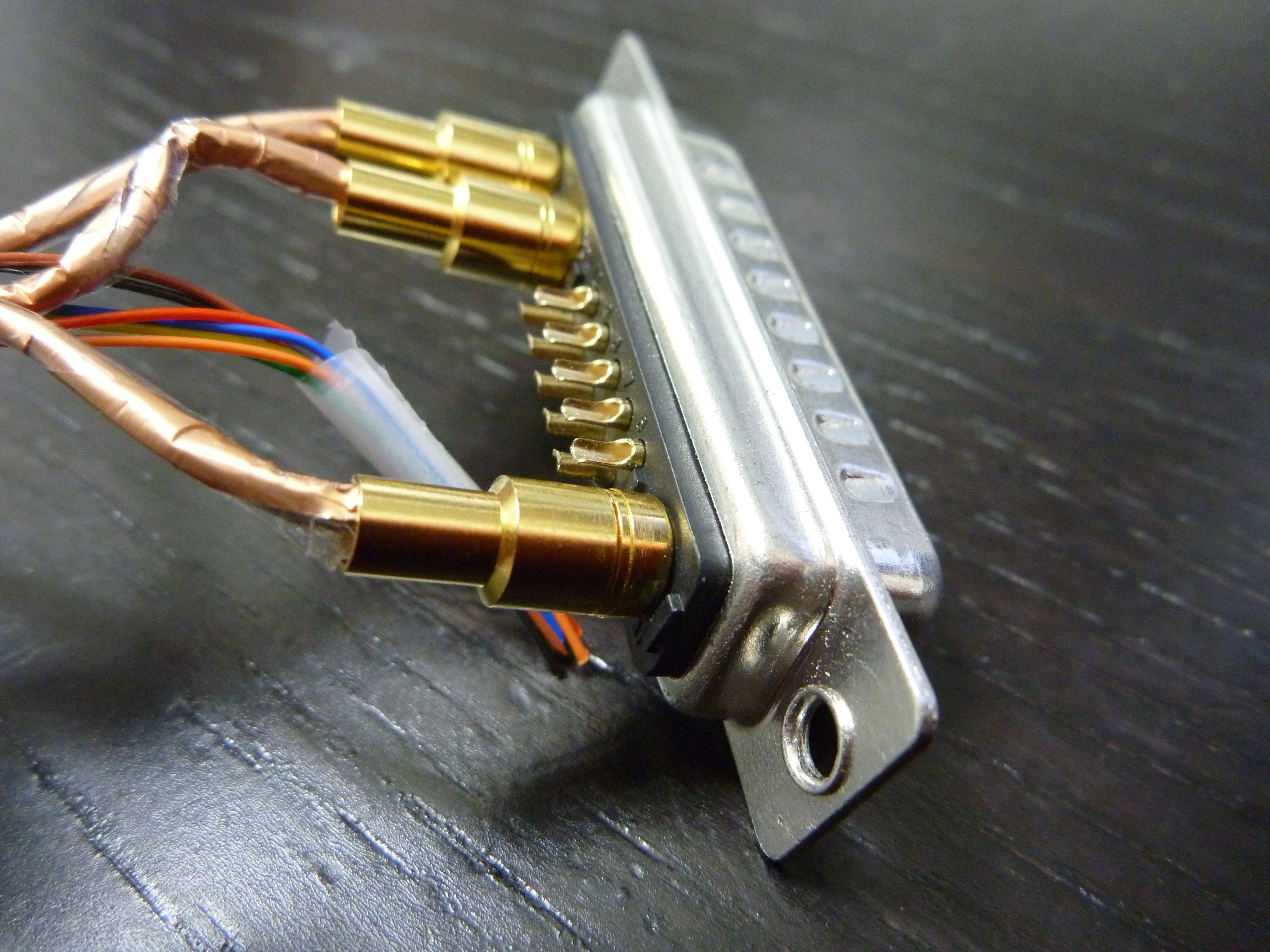
13W3 plugs:
Male plug: this is what goes on your cable.
Note order of BNC: from the left (Blue)A3, (Green)A2, (Red)A1

Female socket – this is what your SGI Workstation already has.
Note order of BNC: from the left (Red)A1, Green(A2), Blue(A3)

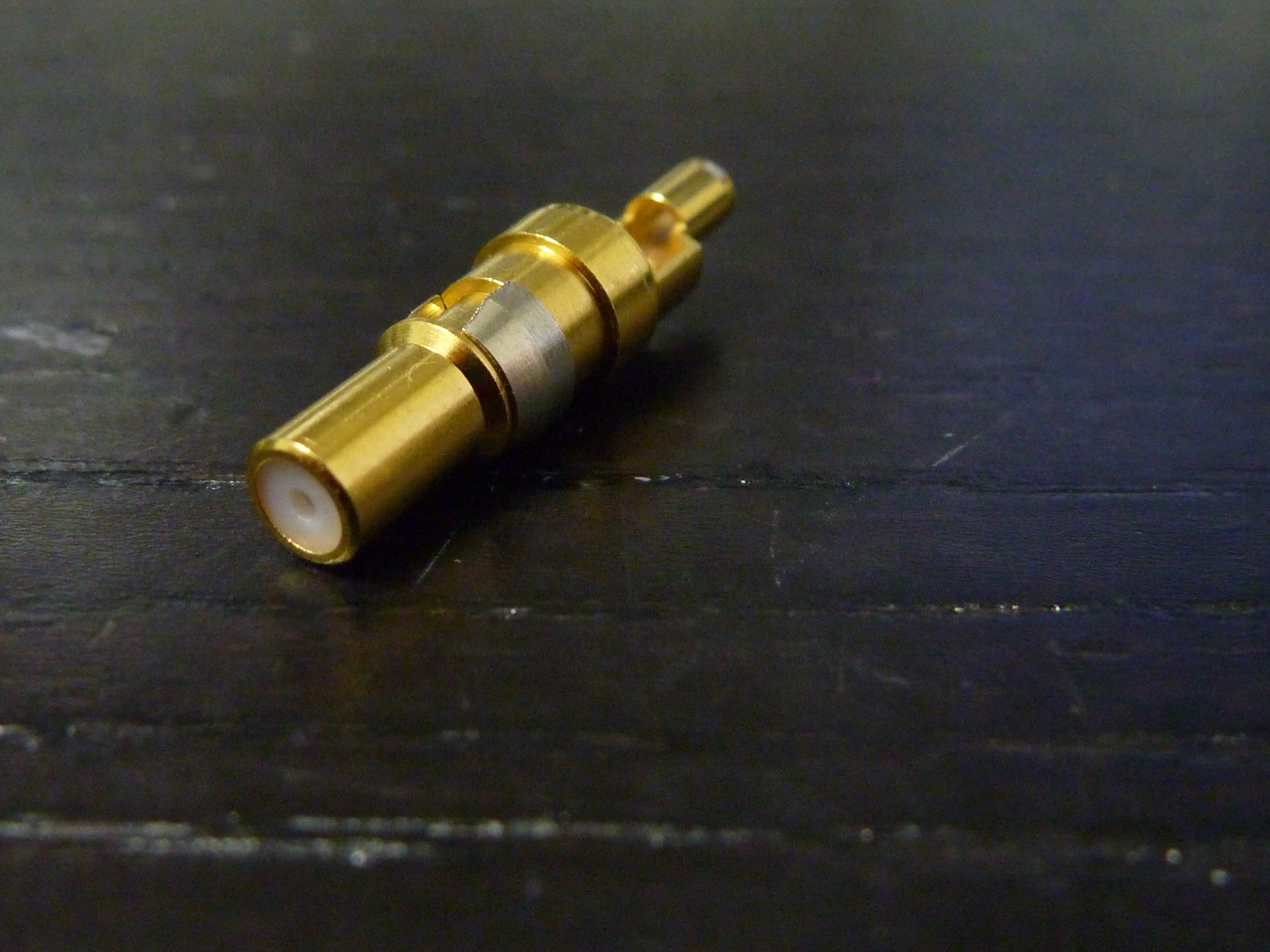
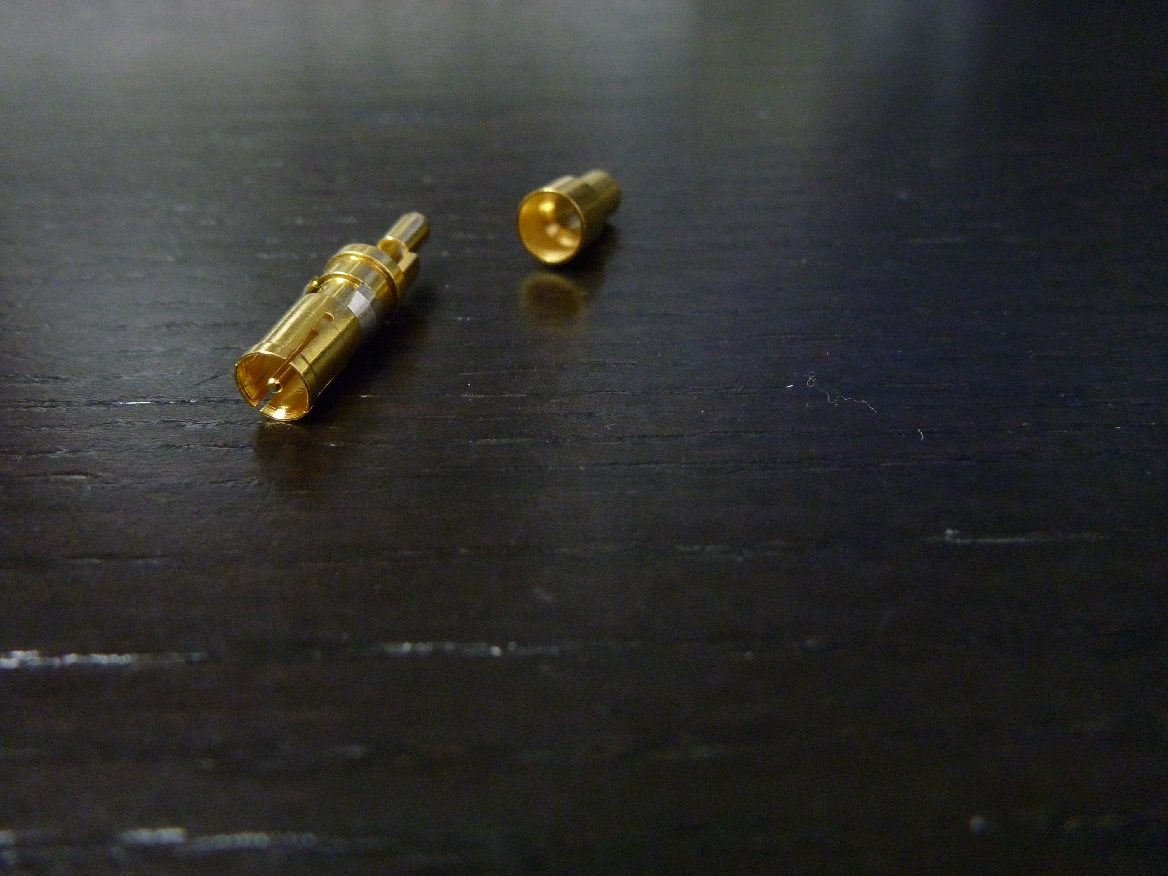
Mini-BNC: this is what goes into your plug assembly – you can see the inner soldering point. Please also note the latch – once you insert into the assembly it’s permanent.
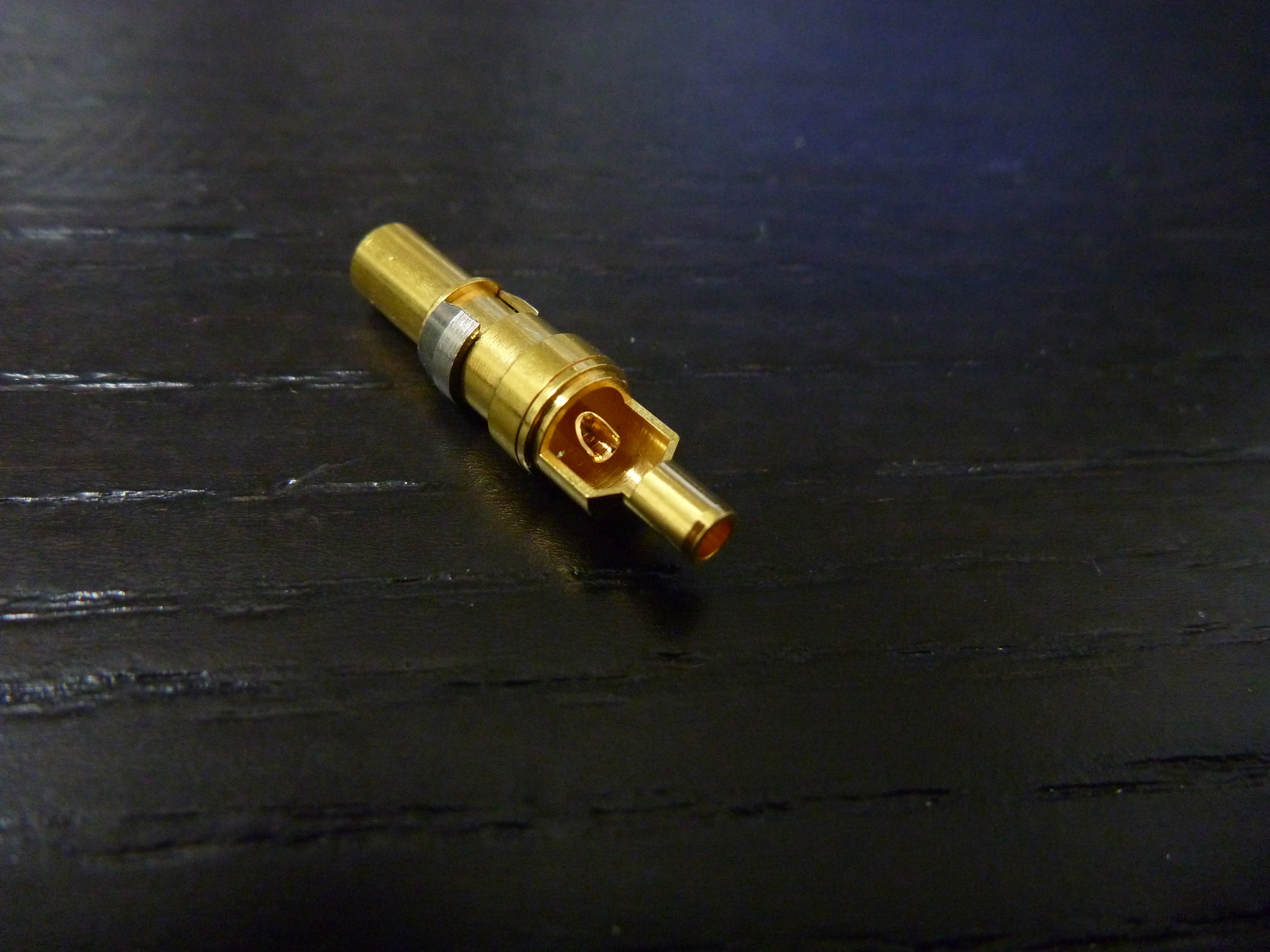
And the front
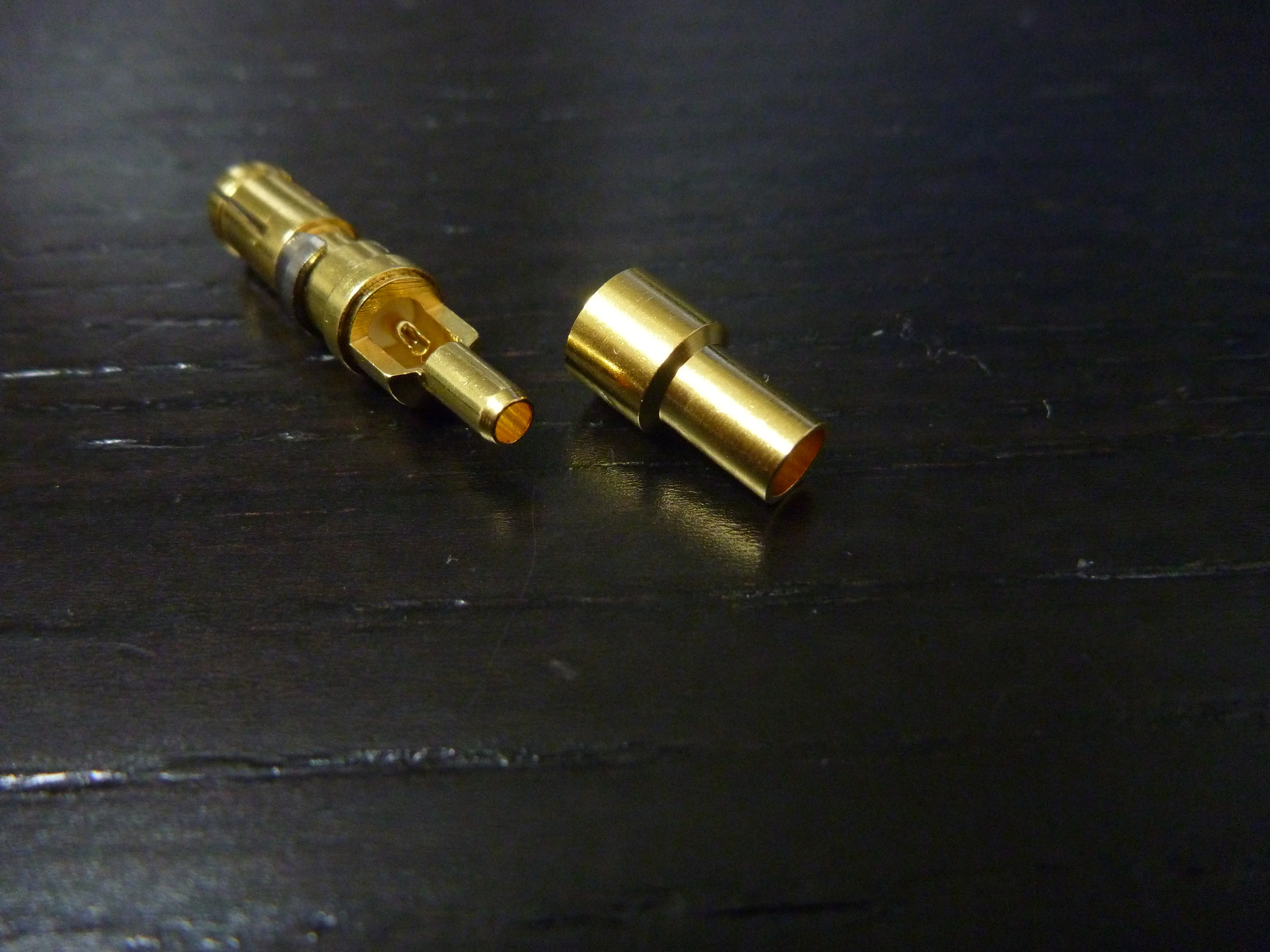
This is how the protective cap looks like – put it on the signal cable BEFORE soldering, and then after filing the outer solder a bit – push to fit – it should click, there’s no need to solder the cap together with the BNC.
The below is the MALE part – this is what your Workstation already has.
And this is how it looks when finished (here with protective cap off)
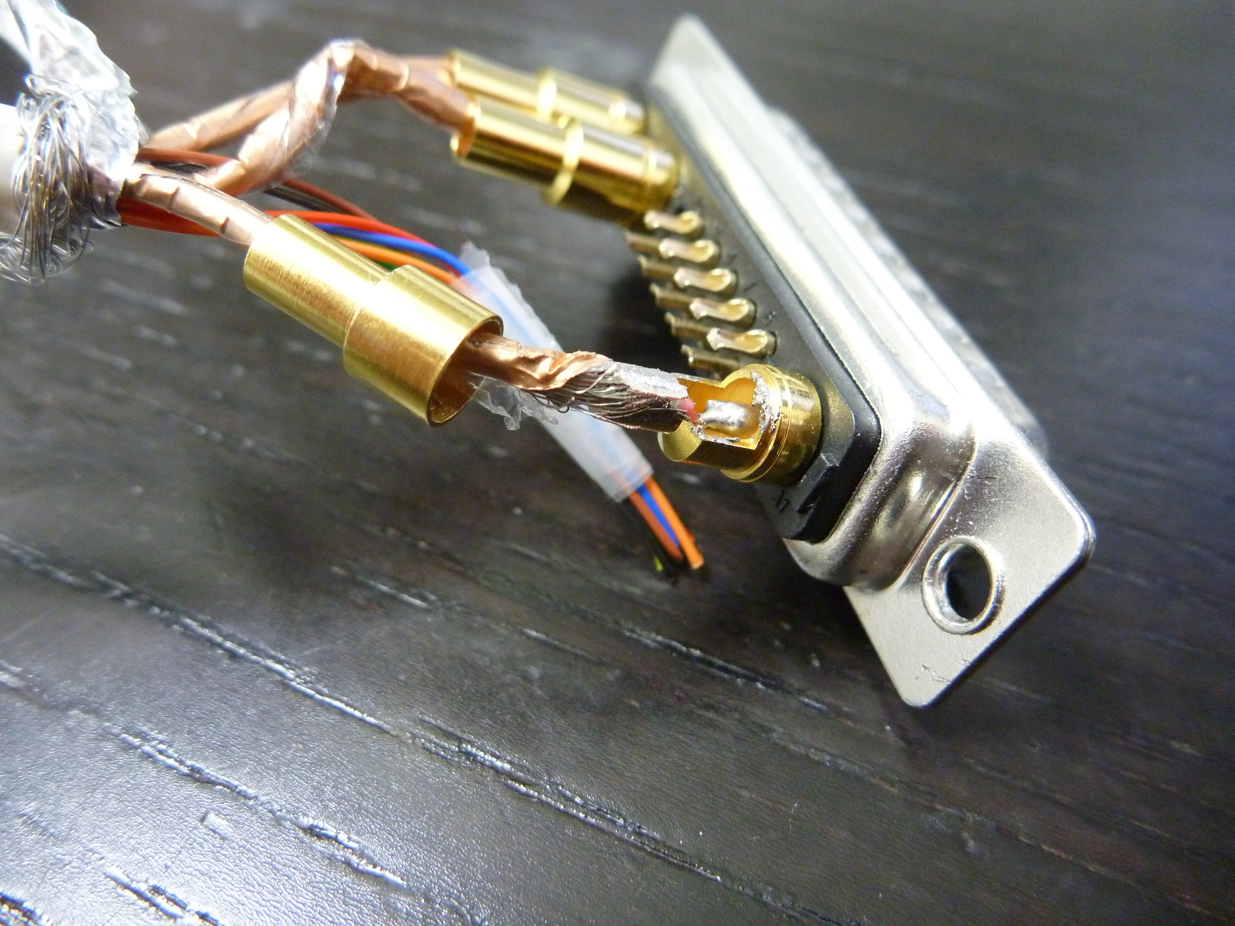
Here ready to be closed and used.