All posts by Kuba Tyszko

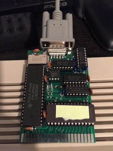
Commodore 64 UART Cartridge

I’ve always been a big fan of serial ports, modems and especially computer-to-computer null-modem communication,

I wanted my Commodore 64 to be able to serve as a serial terminal, but the built-in serial port has extremely low speed.

I found this project, called UART Cartridge, and I knew this is it, of course those carts are not possible to buy, I had to make them myself, so I got to work.

I’ve ordered the PCB’s, all the parts (some still haven’t arrived so I had to find alternative source), and built the first cart already.

The result is amazing, the cart looks great and works really well as well.
IMG_3875.jpeg

I’ve been using my C64 on a Dell U2410 monitor over Composite cable, and the result wasn’t very good,

as much as games look okay scaled, the small very sharp font doesn’t stretch well, so I had to look for other solutions.
IMG_3873.jpeg

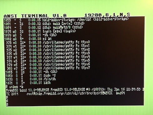
First, I tried Japan-made EntaVision S-Video->VGA converter, with mixed results, the font is more readable but somehow it doesn’t handle interlacing well and everything looks jittery.
IMG_3876.jpeg

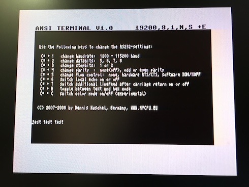
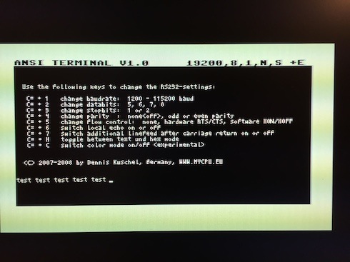
Then, I tried “UP Empire SD-CSH1” S-Video -> HDMI converter and the result is much better, the font is very readable, although on my Monitor I can’t adjust the 720p/1080p picture to 4:3 aspect ratio, well, with such a small font it might be even better to keep it stretched – makes it even more readable.
IMG_3879-1.jpeg

The schematics and design was done by Dennis Kuschel, and are available on his website:

http://mycpu.selfhost.it/otherprojects/c64terminal/index.htm

I have enough parts to make a few more of those carts (and another part order pending), and will happily do so if you’re interested.

I would ship from Japan, it seems that worldwide shipping ranges between $4 and $8 depending on the speed.

Please contact me if you’d like to place an order (for tracking purposes I would recommend registering on my blog and placing a comment – also that other folks can see what is the demand).

Cost for a single unit : $40

Cost for 2-5 units: $35 each

Waiting time from placing an order to shipment – 2-4 weeks (although I will try to keep a small stock of ready-made carts or at least part sets for immediate assembly).

Please note that *your* cartridge may look different, due to supply of certain parts, some of them may be substituted for others.

The cartridges are fully tested on a PAL (EU) Commodore 64.

I have verified that the software itself works on an NTSC Commodore 64 with help of an emulator (VICE), there is no 100% guarantee that it will work on an actual NTSC C64 – and I will not accept returns should that be the case.
Back in business

After a very long period of slacking off in my camera endeavours, I’m back!

I expanded my camera collection quite a bit, so it’s time for pictures,

Voigtlander VITO II – Color-Skopar f/3.5 50mm,

Kodak Tri-x 400 shot at 1600, stand-developed in Rodinal 1:100 for 2 hours.

vitoScan-141003-0003.jpg

vitoScan-141004-0002.jpg

vitoScan-141004-0006.jpg

Ride to Ushimado

Ride to Ushimado near Okayama. 95km in 6 hours.

Strava log

Planned route, stupid Garmin Edge500 lost 2/3 of my GPS data of the actual ride (at least it kept the distance)…

Screen Shot 2013-04-22 at 9.44.07 PM.png

Passing by Okayama Castle

P1030365.JPG

Almost no traffic, blue skies and open space

IMG_1719.JPG

Palm trees

IMG_1725.JPG

Ushimado Yacht Club

IMG_1727.JPG

Nothing better than “secret” road along the coast, 1 car passed over quite a long distance

IMG_1729.JPG

And the coast

IMG_1731.JPG

Dear thief, don’t steal bamboo sprouts !!!

IMG_1732.JPG

Nice finish to the ride, found a 11km running path along the river

IMG_1733.JPG

IMG_1735.JPG

DIY 13W3 to VGA(D-SUB) adapter

While waiting for my Octane2 to arrive, I started preparations and made myself a 13W3 to DSUB Adapter.

There are plenty of adapters on the market, but most of them are either:

  • wrong way (to use 13W3 monitor with VGA Video card)
  • SUN-specific (some of them work with older SGI machines, but due to wrong routing of a couple signals, those do not work with newer machines like Octane)
  • There are (but difficult to find) SGI-specific adapters with only A1,A2,A3 signals routed.

So, what to do – there are usually few options:

  • Buy SUN adapter, and modify it to work (this usually involves dissecting the molded plug and rerouting some cables inside).
  • Buy a 13W3 -> BNC adapter, along with BNC -> VGA (that’s the best solution if you have monitor with BNC).
  • Make your own :)

Being a DIY guy, I decided to sacrifice some cheap old VGA cable I found in the box, bought a couple of 13W3 plugs with mini-BNC’s and started soldering. I was actually surprised I could buy 13W3 plugs, sockets and those mini-BNC’s with no problem at all (I did have to ask the clerk for more because the boxes in the store were empty – they had a bunch in stock – if I recall, 100 JPY for each mini-BNC + 300 JPY for the plug).


The operation is fairly simple:


  1. Strip off the D-SUB cable on one end – if it’s molded be careful not to cut yourself – there will probably be metal shielding which really likes to cut your fingertips :P (which hurts A LOT).
  2. Find out which cables are for R,G,B and their shielding – even my cheap cable had them clearly separated each with it’s own shielding (if yours doesn’t – throw it away and buy another one – you won’t get good picture without each color properly shielded), Red had pink color, Blue was Blue, and Green was white – so finding out what is what wasn’t hard either.
  3. Put BNC protective caps first and strip off the shielding from each of those 3 cables. My cable had foil with outer plastic wrapping on each.
  4. Make sure you have the caps – otherwise you will end up desoldering and probably melting the cable.
  5. Do you really have the caps on ?
  6. Solder the signal cables into 13W3 mini-BNC’s, then wrap the shielding around nicely and solder into each BNC outer casing,
  7. You may need to file the shielding solder nice and round so that cap has snug fit – if you do it well, it will fit all the way with a little click at the end.

I didn’t buy the plastic enclosure yet, looking at dimensions of my plug, any DB25 sized should work.

My small advice – DO NOT insert mini-BNC’s into the plug (I was tempted and this made it a bit harder, also you can’t remove it once it’s in place), solder them while loose.

Use third hand – if you do put mini-BNC’s into the plug – they rotate which just makes it harder.

At every step, make sure you didn’t melt signal’s isolation and there is no short between any of the pins.

Once you’re done, verify the cable:

  • A1 (RED) signal should lead to pin 1 (top left) on the DSUB.
  • A1 (RED) shielding should lead to pin 6 (middle row left) on the DSUB.
  • A2 (GREEN) signal should lead to pin 2 (top 2nd from the left) on the DSUB.
  • A2 (GREEN) shielding should lead to pin 7 (middle row 2nd from the left) on the DSUB.
  • A3 (BLUE) signal should lead to pin 3 (top 3rd from the left) on the DSUB.
  • A3 (BLUE) shielding should lead to pin 8 (middle row 3rd from the left) on the DSUB.


That’s all – 3 shielded cables should to the trick.

In addition, I would also recommend soldering cable’s outer shielding into the metal casing of the plug. (If you don’t – it will probably work, but you will end up with some interference.)

If you fancy (or if you monitor doesn’t support Sync-On-Green), you may need to solder Sync signals into respective ports (I didn’t need to, and this has not been confirmed to work):

Pin 3 – C. Sync / Gnd goes to pin 10 on DSUB

Pin 4 – H. Sync goes to pin 13 on DSUB

Pin 5 – V. Sync goes to pin 14 on DSUB


Some pictures below:

13W3 plugs:

Male plug: this is what goes on your cable.

Note order of BNC: from the left (Blue)A3, (Green)A2, (Red)A1

plug_13w3_numbers2.JPG

Female socket – this is what your SGI Workstation already has.

Note order of BNC: from the left (Red)A1, Green(A2), Blue(A3)

socket_13w3_numbers.JPG


Mini-BNC: this is what goes into your plug assembly – you can see the inner soldering point. Please also note the latch – once you insert into the assembly it’s permanent.

plug_bnc_back.JPG

And the front

plug_bnc_front.JPG

This is how the protective cap looks like – put it on the signal cable BEFORE soldering, and then after filing the outer solder a bit – push to fit – it should click, there’s no need to solder the cap together with the BNC.

socket_bnc_back_cover.JPG

The below is the MALE part – this is what your Workstation already has.

socket_bnc_front.JPG


And this is how it looks when finished (here with protective cap off)


bnc_cap_closeup.JPG

Here ready to be closed and used.

done_soldering_bnc_with_caps.JPG